


General
Switching distance
The switching distance between a sensor and a magnet or any other target to be detected depends on:
- Sensing characteristics of the sensor
- Magnet material
- Magnet dimensions
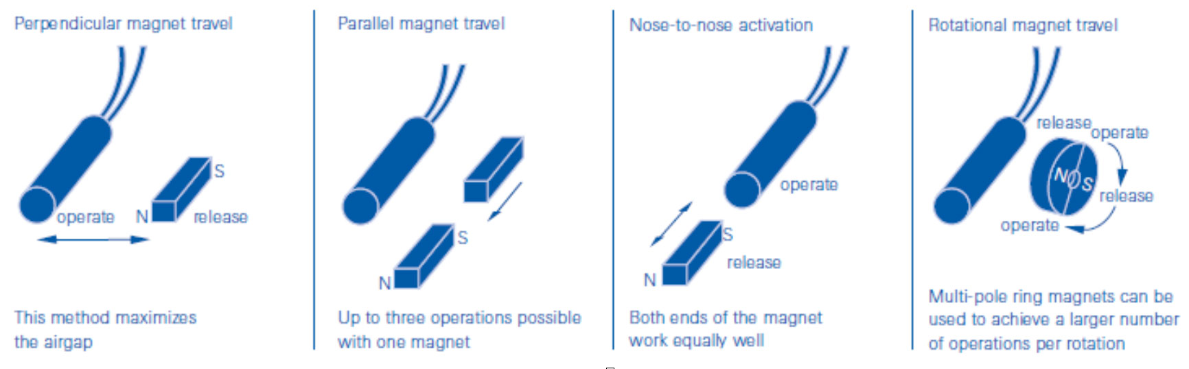
- Relative motion of the magnet with respect to the sensor
- Presence of nearby magnetic or ferrous materials
ESD sensitivity
- Reed sensors are not solid-state devices and thus immune to ESD
- Several of our Hall sensors are equipped with additional circuitry to enhance ESD immunity. They have been tested for ESD immunity in accordance with IEC publication 1000-4-2 using testing standard EN50082-2.
Sensors without this additional circuitry should be handled like other ESD-sensitive devices.
Current sink interfacing
3-wire interface
Sinking outputs are often used in negative logic applications, where a low signal is required for an active state. There, sinking outputs normally have current flowing into the device output lead when the device is active. Also called “open collector outputs”, sinking outputs are compatible with any logic family because they can be used for a wide range of supply and output voltages. Furthermore, the supply voltage used to power the Hall assembly may differ from the pull-up voltage to which it is connected.
The external pull-up resistor connected between the output and supply voltage is required for proper operation. With the resistor connected as shown, the output will be “pulled up” to the supply voltage (Vcc) level when off and (approximately) to ground when on.

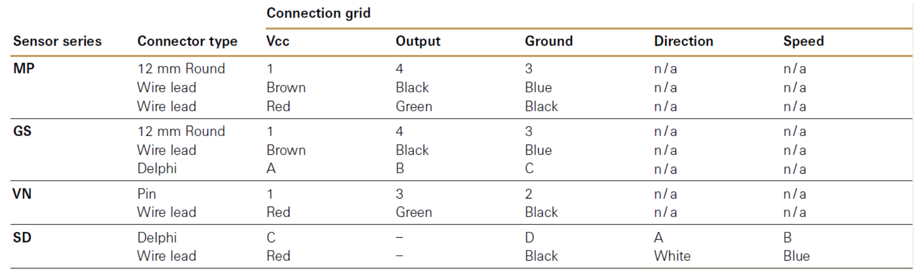
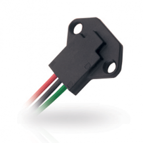
Connection / interfaces
Depending on the type and version, the sensors are equipped either with a defined standard connector or with wire leads for individual connection.
Housing
ZF sensors are delivered in ready-for-assembly housings for the indicated protection class.
Operating life
As a solid-state device with no moving parts, the operating life a ZF hall sensor is virtually unlimited.
Magnetic proximity sensors
Magnetic proximity sensors
Magnetic proximity sensors are used for the non-contact – and thus wear-free – sensing of position and movement. ZF offers standard product solutions based on Hall and Reed technology.
Hall or Reed?
Although both types of sensor detect the proximity of magnets, Hall and Reed sensors differ greatly in the way they function. Hall sensors are solid-state devices whose output changes when exposed to a magnetic field. Reed sensors, on the other hand, are electrically switched with two tiny contacts in a vacuum tube that open or close in the absence or presence of a magnetic field. In many applications, either device could be used, but there are also some situations where one technology may be preferable over the other.
A Hall effect sensor may be preferable to a reed sensor if you have the following requirements:
- Unlimited life. For example, if you are interested in sensing a spinning magnet that will operate a sensor billions of times, you should consider a Hall effect sensor. Reed sensors generally have very long life compared to other electro-mechanical devices, but they cannot match the virtually infinite life of a Hall effect sensor.
- Your application can’t tolerate any contact bounce.
- You’re looking to do geartooth speed sensing or rotary position sensing. A reed sensor is restricted to binary position sensing, and it doesn’t function as a geartooth sensor.
A reed sensor may be preferable to a Hall effect sensor if you have the following requirements:
- You need a two-wire device that requires no power (perhaps to conserve battery power).
- You require immunity to ESD and have a low target price (Cherry does make Hall effect sensors with ESD immunity, but this costs a little more).
- You want to provide a supply voltage that is outside the typical 5 vdc to 24 vdc supply voltage range for Hall effect sensors. For example, reed sensors can effectively switch 110 vac at low current.
Reed sensors
Reed sensors are available in different contact configurations:
Normally open (Form A)
Near a magnetic field, this sensor closes.
Normally closed (Form B)
Near a magnetic field, this sensor opens.
Changeover (Form C)
In the rest position, the circuit between the COM and NC contact is closed. When exposed to a magnetic field, the circuit between the COM and NC contact opens and the circuit between the COM and NO contact closes.
Magnetic poles
Most of the solid state sensors in our standard product line are sensitive only to the South pole of a magnet. The following are the exceptions:
- MP100105 and MP100106, which use GMR sensing elements and which are omnipolar. This means that they can be activated by either a North pole or a South pole
- MP101303 and MP101304, which are bipolar latching sensors. They are latched with a South Pole and unlatched with a North pole
- The MP1021 series, which includes both North pole-sensitive devices and latching devices.
- All of the reed sensors (MP2007 through MP2019), which are omnipolar.
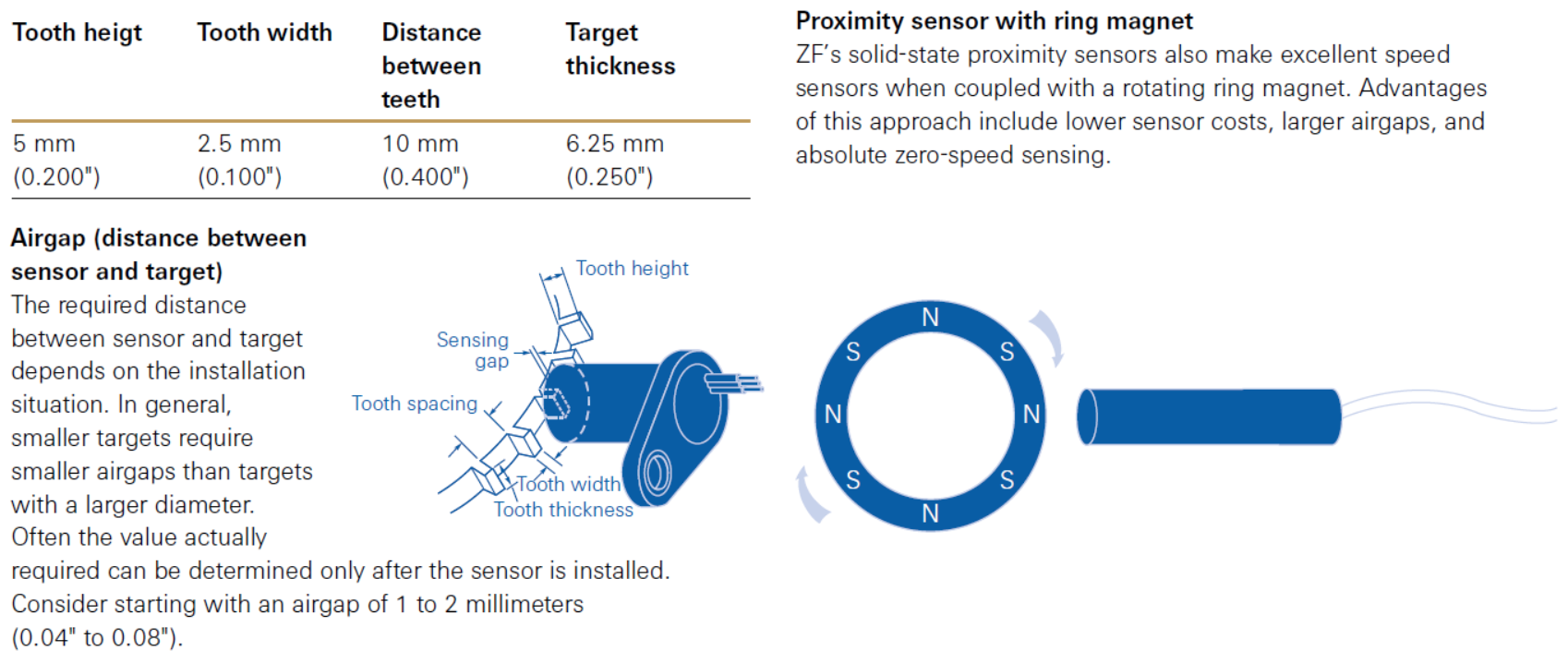
Airgap (distance between sensor and magnet)
The field strength at various points around a permanent magnet is dependent on several factors, including the shape, size, and material of the magnet. Most standard ZF sensors exhibit a similar sensitivity, but there are a few exceptions. The bipolar latching sensors, such as MP101303 and MP102104 have relatively low gauss thresholds, allowing for somewhat wider airgaps. The most sensitive of all are the MP100105 and MP100106, which use a highly sensitive GMR sensing element. These two devices are also omnipolar, meaning that they’re indifferent to the polarity of your magnet.
Switching hysteresis
The switching hysteresis is determined by the difference between the activation point as the magnet moves toward the sensor and the deactivation point as the magnet moves away from the sensor.
Geartooth sensors
Geartooth sensors
The geartooth sensor category includes both speed sensors and combination speed and direction sensors.
Speed and direction measurement
Sensors in the SD series provide both speed and direction information. SD series sensors incorporate two Hall-effect ICs that are slightly offset from one other. The resulting minimum phase distance between the two signals is analyzed by means of internal conditioning logic and the direction of the target rotation is determined. The information is output via two digital outputs. These outputs use an open collector (sinking) output. The speed signal switches from high (Vcc) to low (near zero) when it detects a transition from “no-tooth” to “tooth present”.
The direction signal, which is output at a separate pin, is high when gear rotation is clockwise and low when gear rotation is counter-clockwise.
Operating a speed sensor
Although commonly known as geartooth sensors, solidstate speed sensors not only sense the speed of gearteeth but are also suitable for detecting the rotations and motion of various targets with some type of discontinuous surface, provided that they are magnetically conductive.
Examples of appropriate targets include:
- Sprockets
- Bolt head
- Roller chains
- Cavities in smooth surfaces
Ferromagnetic materials are most suitable as targets to be measured. We recommend iron or steel. Other factors that influence sensor performance include target shape, geartooth height, and the distance between teeth.
Orientation
GS series sensors are not orientation-sensitive. SD series speed and direction sensors do have an orientation requirement, and the appropriate orientation is noted on the housing.
To adjust the alignment to your customized gear, please contact us.
Frequency
The measuring range depends on the sensor type and the target, but maximum frequency is generally > 10 kHz. Some SD Sensors can measure a frequency up to 20 kHz. The target geometry must be noted when calculating the frequency. With asymmetrical targets, for example, with narrow tooth widths as compared to the distances between teeth, the time between the leading and trailing edge of the tooth is the governing factor. ZF sensors have maximum response times from approximately 10 μS (MP series) to around 50 μS (GS series), due to the response time of the Hall cell. If the required response time is very close to these limits, it can lead to unexpected results, such as lost counts. Unlike passive speed sensors (VR or variable reluctance sensors), a GS sensor has an output amplitude that is independent of input frequency (speed). This means that the sensor does not require a minimum speed. However, it does require some initial movement of the target in order to locate the tooth edge. We therefore prefer to call it a “near-zero-speed” sensor.
Operating life
As a solid-state device with no moving parts, the operating life a ZF speed sensor is virtually unlimited.
Vane sensors
Vane sensors
These sensors are actuated by a vane passing through the fork. The ferromagnetic vane changes the magnetic field between the sensor and the magnet in the two arms of the fork.
Advantages of a Ferrous Vane Sensor over a Typical Opto-Interrupter
There are a few potential advantages, depending upon your application:
- Since opto-interrupters rely on the detection of light, contamination that inhibits the detection of light can interfere with sensor performance. Ferrous vane sensors are immune to dust, dirt and grease.
- We also recommend ferrous vane sensors for their stability at high temperatures. ZF offers standard vane sensors with maximum operating temps up to 125C.
- You should also consider a ferrous vane sensor if your sensor’s ambient environment includes infrared light interference.
Vane material
In general, all ferromagnetic materials are suitable for vanes. We recommend iron or steel.
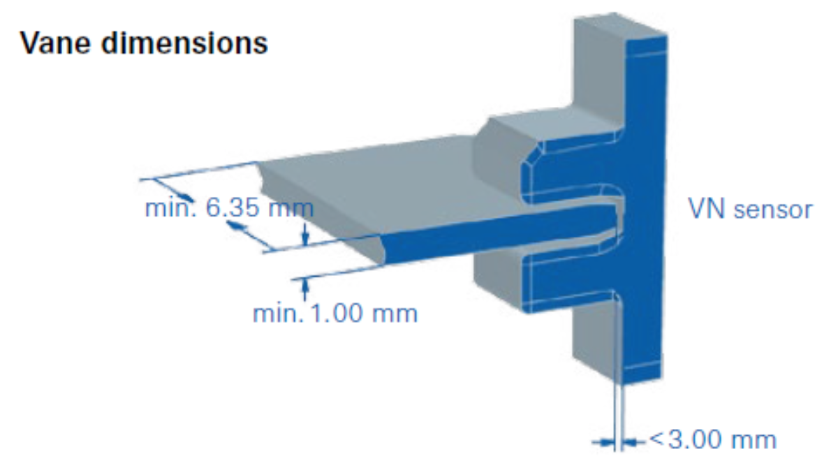
Vane dimensions
We recommend a vane material thickness of at least 1 millimeter and an individual vane width of at least 6.35 millimeters. The vanes should penetrate a depth of less than 3 millimeters from the bottom of the sensor slot.