Position and speed sensor types
Nothing works without sensor technology. Any modern and smart technology relies on precise sensor technology – whether optical sensors, pressure, position, speed, temperature, or acceleration sensors. Their main task is to perceive various chemical and physical properties of the environment or of a target object.
Based on this perception, machines operate autonomously, so the reliability and accuracy of the sensors play a key role in functional security.
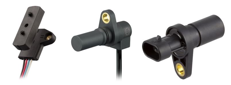
The target of this article is to provide a general understanding of position and speed sensor types with their underlying strengths and weaknesses. Each sensor is suitable for a specific application field. The illustration below shows different sensor principles for position and speed measurement without any claim for completeness.

Technical specifications of position and speed sensors
Due to the vast number of sensor types and versions, it is a great challenge to choose the right sensor for a specific application. First, engineers need to define all relevant requirements which the sensor needs to fulfill. It must fit perfectly to the application, without over specification, and to reach a minimal cost.
In general, sensor specifications can be divided into sensor type, electrical and mechanical characteristics as well as operating conditions. Due to these characteristics, sensors exhibit advantages and disadvantages for different applications. In the following section, several important sensor specifications are presented with explanations and examples.
Sensor type
– Measurement type: Incremental or absolute
– Sensing principle: Optical, magnetic (hall-based, inductive), electromechanical
Electrical characteristics
– Resolution: The smallest change which can be measured
– Repeatability: The stability of the sensor with repeated measurements from the same starting point
– Accuracy: Output veracity in %
– Type of electrical output: Analogue/digital, serial/parallel
– Electrical supply and output voltage/current
Mechanical characteristics
– Geometry: Dimensions, linear, rotary
– Scalability: e.g. 360° angle, 500 mm linear measurement, 20kHz frequency
– Mechanical interfaces: Connector options, wire arrangements, mechanical fixing points
– Air gap (contactless sensors): e.g. 0,4 – 2,2mm
Operating conditions
– Temperature range
– Environmental factors: e.g. dust/particles, humidity, shock, vibration, climate
– Protection classes: e.g. IP, ESD-susceptibility, short circuit strength
Comparison of selected position & speed sensors
The main task of position sensors is the sensing of angular or linear displacements, distances, gaps, distensions and fill levels. The potentiometer as an electromechanical sensor is the most famous but also the oldest sensor type invented by the German physicist Johann Christian Poggendorff in the year 1841. Nowadays, several versions and types of the potentiometer exist. Manufacturers optimized the electromechanical sensor over time continuously to fulfill strict requirements for several new application fields. In addition, contactless sensors conquered the market over time as they have beneficial characteristics compared to the electromechanical potentiometer. These are discussed below.
Speed and frequency sensors are used to measure the covered distance or angle per time unit. A major application field is the speed controlling and monitoring of asynchronous drive systems applied in various industries like on- and off-road vehicles, the energy sector, medical sector, automation and machinery sectors. In this field contactless sensors penetrated the market due to the lack of mechanical parts that wear out, yielding a long lifetime.
In the following section the principle, applications, advantages and disadvantages of selected position and speed sensors are presented and compared.
Potentiometers
Principle
Potentiometers use a resistive element in the form of a mechanical sliding contact for measuring linear or angular displacements. The slider is always in contact with a resistance path. The extent of resistance changes according to the movement of the slider. In addition to the mechanical part, every potentiometer needs an external power source so that the mechanical movement can be converted into an electrical signal. The voltage output depends on the extent of resistance and therefore on the rotation angle or covered distance. The measurement range, output signal and electrical connections are customizable and available by many electrical component manufacturers. Potentiometers provide absolute measuring figures in comparison to incremental sensors, whose measurement system is based on repetitive and periodic graduations.
Strengths
– Low cost (pennies but high precision versions may cost up to $200)
– Flexibility in installation and characteristics
– No internal electronic components necessary
– Fast prototyping
– Availability by many manufacturers
– High resolution and accurate measurement (output veracity better than 1%)
– Redundancy for security-reliable signals
– Operating temperature range up to 250°C
– Measurement of large displacement (up to 360°; 1,500mm)
Weaknesses
– Susceptible to wear, especially in high vibration environments (e.g. road vehicles, heavy plants or aircraft system)
– Susceptible to foreign particles such as dust/sand which will abrade the resistive track (lifetime is reduced dramatically)
– Limited lifetime due to wear which can be rated for 500,000 cycles in average
– Not suitable for operation in liquids
– Not suitable for high accelerations (slider can separate)
– Digital converter is necessary, increasing cost
– Limited miniaturization which may limit available measuring scope
Application fields
In general, potentiometers are rather suitable for applications with modest duty cycles and benign environments. The requirements of applications should not be severe due to wear and friction of the mechanical slider.
As potentiometers exist in a diversity of different versions with the advantage of low-price and widespread availability, they can be found in nearly every industry sector.
Inductive encoders
Principle
An inductive Encoder also known as an Incoder, is a contactless speed and positioning sensor suitable for linear and angular displacements. Based on the principle of electromagnetic induction the sensor measures, for example, in engines the position of a rotor relative to a stator. Main components of an inductive sensor are spools (traditional Incoder) or printed circuits on substrates (Incoder of a new generation). When a metal target approximates the inductor a change of magnetic field happens. From the law of induction, the sensor creates a voltage between the bipolar outlet, which is proportional to the temporal changing of a magnetic flux. This triggers a current which flows through the inductor and connected wires to the output device. The sensing range depends on the type of target material; ferrous metals allow a longer sensing range than nonferrous metals. The electronics can be placed away from the sensing area which allows for the use of the Incoder in rough environments.
Strengths
– Safe and reliable operation also in tough conditions
– Contactless and free from wear
– Multiple geometries such as curvilinear, 2D & 3D position sensing
– For wide and small measuring ranges
– Operating temperature range up to 150°C
– High accuracy (based on a scale of 360° up to 0,09°)
– New generation: Multi layers of thin sensors for redundant signals
– High EMV resistance
– Electronics can be located away from sensing area, – no protection necessary
Weaknesses
– Traditional Incoder: Big size due to spooling and no redundancy measurement
– New generation: Cost factor
– Not suitable for low speed measurements (output signal depends on frequency)
– Susceptible to air gap variation
Application fields
– Monitoring and controlling of safety related position applications (machinery manufacturing, plant engineering, on and off-road vehicles)
– Storing and handling technologies
– Engine & wheel speed sensor, diesel injection pump, cam shaft sensor
– Inductive engine tachometer (cranked shaft frequency sensor)
Hall-based sensors

Principle
Hall effect sensors are highly sensitive to magnetic fields. They can be used for linear and rotary measurements as well as for speed and direction sensing. The main component of these sensors is the Hall IC and the underlying permanent magnet. The Hall effect is based on thin semiconductor chips. If such a current-carrying plate is penetrated vertically by an induction, B (permanent magnet), charge carriers are deflected by the Lorentz force perpendicular to the field. The current, I, provided by an external power supply is deflected from its otherwise straight path. So, a voltage, U, can be detected which occurs across the current direction between two opposite edge points of the plate. The output voltage, U, is proportional to the induction, B and the current, I.
The magnetic field created by the permanent magnet is influenced as soon as an external ferromagnetic material approaches the sensor. Especially for speed sensing, the specifications of the target wheel and the air gap need to be compatible with the Hall sensor.
Due to this principle, the sensor operation draws a continuous current supplied by an external power source. That’s the reason why Hall sensors are considered active sensors, as they need integrated electronics? for signal processing. In direct contrast to the physical phenomena of induction, the Hall effect occurs under steady state conditions. The output voltage of the Hall IC persists even when the magnetic field is constant over time.
Strengths
– True solid state, no moving parts, no wear and tear from friction
– Virtual unlimited life (billion range of operations)
– High speed operation – over 100kHz possible
– Operates with stationary input (zero speed)
– Broad temperature range (-40 to +150°C)
– Highly repeatable operation
– Small size (physically fits into many applications where other magnetic transducers would be too bulky)
– Ruggedness: Immune to shock and vibration, highly resistant to moisture and environmental contaminations
– Can detect direction of a field as well as its magnitude
– Cost effective
– Different types provide digital, analog, or programmable output
– 2, 3 or 4 wire configurations available
Weaknesses
– Sensors are ESD sensitive and magnetic flux from their surroundings (e.g. wires) can render results inaccurate
– Handles only DC loads
– Continuous current consumption is needed
– Needs integrated circuitry
Application fields
– Successfully used in hostile environments such as inside automotive transmissions and down the bore-hole in oil well drilling equipment
– Speed of wheels and shafts, such as speed measuring, combustion engine ignition timing, anti-lock braking systems
– DC electric motors to detect the position of the permanent magnet
– Power Plants/Wind energy: Turbine speed
– Angular sensors for steering and pedal systems for Off-Road vehicles
– ABS systems and speed measuring in E-Bikes
Optical Encoder
Principle
Optical sensors are usually known as encoders and incremental position sensors for angular and linear measurements. They are also suitable for speed sensing. Main components are an LED, a turning and optical disk with a reference mark, and as a photo sensor with a squaring circuit. A generated light beam provided by the LED is shone through or onto a grating of the optical disk. The resulting light is measured by a photo sensor and is automatically converted into a digital output.
Strengths
– Rotary encoders can achieve 50 – 5,000 counts per revolution
– High accuracy if mounted precisely
– Low sensor weight
– Lifetime 80k – 100k hours
– Not susceptible to ferromagnetic materials
Weaknesses
– In robust environment measurements might fail when the lens or optical disk becomes concealed by foreign particles such as water, dirt or swarf.
– Susceptible to shock
– Little or no warning of imminent failure
– Limited operating temperature range (70°C maximum)
Application fields
– Position as well as speed and direction measurement
– Applications which need high counts per revolution within a benign environment
– Suitable in environments/applications with ferromagnetic materials
Reed switch

Principle
The reed switch was invented by Bell Labs in the 1930s. Within ten years it began to find applications widely as a position sensor in electronic and test equipment. In contrast to the other mentioned sensors in this article, the reed switch can only detect the end position of a target or it can be used as a speed sensor as it counts switching operation over time. The basic reed switch consists of two ferromagnetic nickel-iron wires which are located inside a hermetically sealed glass capsule. The two wires are formed into “reeds” by flattening one end. The reed ends are carefully aligned with a small overlap. The glass capsule is filled with inert nitrogen. The reeds act as magnetic flux conductors when exposed to an external magnetic field. Poles of opposite polarity are created at the contact gap and the contacts close when the magnetic force exceeds the spring force of the reeds. The contacts open when the external magnetic field is reduced so that the magnetic attractive force between the reeds is less than the restoring spring force of the reeds.
Strengths
– Zero power consumption (no external power required)
– Cycle life is typically in the millions of operations
– Cost effective
– Hermetically sealed: Immune to dust/particles, water and moisture
– Reed switches are available in a variety of sizes with different ampere turns and hysteresis regarding magnet distance and magnet size
– Switching power: Handles both AC and DC loads, ability to switch from 10 nanovolts to 10,000 Volts and up to 5 Amps
– Immune to electrostatic discharge (ESD)
– Operating temperature ranges up to 200°C
Weaknesses
– Susceptible to vibration/shock above approximately 20g
– Can experience a change in sensitivity due to mechanical stress
– Speed measurement limited to operations below 1kHz
– Digital output (only end position detection)
Application fields
– Position sensing (end position of a movement, only digital output)
– Speed measuring (counting switches)
– Relay applications (electronic instrumentation applications)
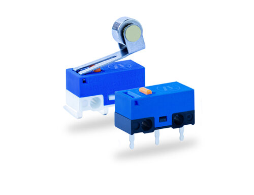
– Automotive and transportation (brake fluid sensor, headlights and taillights, mirror controls, crash safety sensing, tire pressure monitoring, gas cap detection)
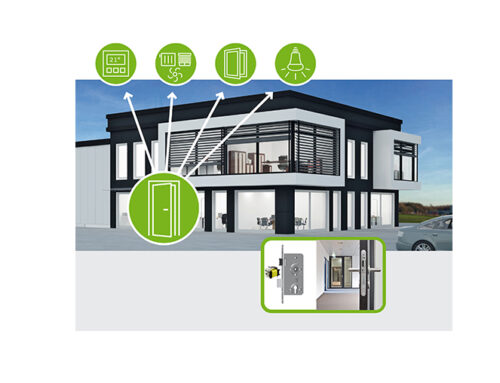
– Smart Home (security systems, white goods, HVAC and plumbing)
– Safety and security (fire alarms, door sensors, window sensor, hotel security)
– Medical, telecommunication, test and measurement applications
Summary
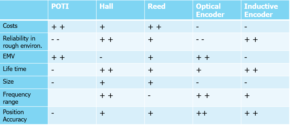
All the presented sensors show different characteristics based on their physical principle so that there is no best sensor solution. It always depends on the respective application field. The following table gives a rough position and speed sensor comparison in terms of several key performance indicators. The evaluation is based on standard sensors of the particular sensor types as described above.
